1.
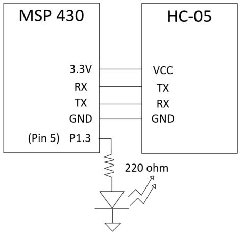
MSP430 Communicates with HC-05 Bluetooth module
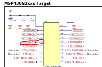
Use P1.3 as the digital output pin to control the LED.
Make the following hardware connections.
Upload the following sketch to your MSP430.
//Example 1, use HC-08 to control an LED connected to MSP430
char val; // variable to receive data from the serial port
int ledpin = 5; // LED connected to pin 5
void setup() {
pinMode(ledpin, OUTPUT); // pin 48 (on-board LED) as OUTPUT
Serial.begin(9600); // start
serial communication at 9600bps
}
void loop() {
if( Serial.available() ) //
if data is available to read
{
val =
Serial.read(); // read
it and store it in 'val'
}
if( val == 'H'
)
// if 'H' was received
{
digitalWrite(ledpin, HIGH); // turn ON the LED
} else {
digitalWrite(ledpin, LOW); // otherwise
turn it OFF
}
delay(1000);
// wait 100ms for next reading
}
Download a Bluetooh Serial Terminal App to your phone. If you uses an
IPhone there must be an alternative to this App.
Connect your Phone to HC-05 from Settings and from the App. The
demonstration follows. If the phone asks you the password, try 1234.
2. Voice command to control an LED
Download a different APP called 'Arduino Voice Control' to your phone. There might be an alternative if you use an iphone.
No changes to the hardware connection compared to the one in Section 1.
Use the following code for this new experiment.
Code:
//Example 2, Voice commands
String voice;
int ledpin = 5;
void loop() { while
(Serial.available()){ //Check if there is an
available byte to
read
delay(10);
//Delay added to make thing stable
char c =
Serial.read(); //Conduct a serial read
if (c == '#')
{break;} //Exit the loop when the #
is detected after the word
voice +=
c;
//Shorthand for voice = voice + c
}
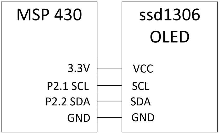
The display module being used in this experiment is:
IZOKEE 0.96'' I2C IIC 12864 128X64 Pixel OLED LCD Display. The module
uses a Shield Board Module SSD1306 Chip.
The datasheet of the ssd1306 module can be downloaded here.
From the pinout of the module you can tell the module has a digital
controller inside which provides I2C communication ports SCL and SDA.
This is great news because it doesn't occupy many pins of the MSP430
chip.
A quick example can get you started. Download it
here
and run it on your board. Run a successful code right after you have
the hardware connected can let you verify the hardware connection
before you move too far in your customized code.
A quick demonstration video can be found here:
If we only need to display text on it, use the following code:
// Example 4, Display texts, works #include <Wire.h> #include "Font.h" #include <string.h> #include "images.h"
#define OLED_Write_Address 0x3C
void OLED_Data(char *DATA) /* Function for sending data to OLED */ { int len = strlen(DATA); for (int g=0; g<len; g++) { for (int index=0; index<5; index++) { Wire.beginTransmission(OLED_Write_Address); /* Begin transmission to slave device */ /* Queue data to be transmitted */ Wire.write(0x40); /* For Data Transmission, C = 0 and D/C = 1 */ Wire.write(ASCII[DATA[g] - 0x20][index]); Wire.endTransmission(); /* Transmit the queued bytes and end transmission to slave device */ } } }
void OLED_Command(char DATA) /* Function for sending command to OLED */ { Wire.beginTransmission(OLED_Write_Address); /* Begin transmission to slave device */ /* Queue data to be transmitted */ Wire.write(0x00); /* For Data Transmission, C = 0 and D/C = 0 */ Wire.write(DATA); Wire.endTransmission(); /* Transmit the queued bytes and end transmission to slave device */ }
void OLED_clear() /* Function for clearing OLED */ { OLED_setXY(0x00, 0x7F,
0x00, 0x07); /* Column Start Address 0, Column End Address 127, Page
Start Address 0, Page End Address 7 */ for (int k=0; k<=1023; k++) { Wire.beginTransmission(OLED_Write_Address); /* Begin transmission to slave device */ /* Queue data to be transmitted */ Wire.write(0x40); /* For Data Transmission, C = 0 and D/C = 1 */ Wire.write(0x00); Wire.endTransmission(); /* Transmit the queued bytes and end transmission to slave device */ } }
void OLED_setXY(char
col_start, char col_end, char page_start, char page_end) /* Function
for setting cursor for writing data */ { Wire.beginTransmission(OLED_Write_Address); /* Begin transmission to slave device */ /* Queue data to be transmitted */ Wire.write(0x00); /* For Data Transmission, C = 0 and D/C = 0 */ Wire.write(0x21); /* Set Column Start and End Address */ Wire.write(col_start); /* Column Start Address col_start */ Wire.write(col_end); /* Column End Address col_end */ Wire.write(0x22); /* Set Page Start and End Address */ Wire.write(page_start); /* Page Start Address page_start */ Wire.write(page_end); /* Page End Address page_end */ Wire.endTransmission(); /* Transmit the queued bytes and end transmission to slave device */ }
void OLED_init(void) /* Function for initializing OLED */ { OLED_Command(0xAE); /* Entire Display OFF */ OLED_Command(0xD5); /* Set Display Clock Divide Ratio and Oscillator Frequency */ OLED_Command(0x80); /* Default Setting for Display Clock Divide Ratio and Oscillator Frequency that is recommended */ OLED_Command(0xA8); /* Set Multiplex Ratio */ OLED_Command(0x3F); /* 64 COM lines */ OLED_Command(0xD3); /* Set display offset */ OLED_Command(0x00); /* 0 offset */ OLED_Command(0x40); /* Set first line as the start line of the display */ OLED_Command(0x8D); /* Charge pump */ OLED_Command(0x14); /* Enable charge dump during display on */ OLED_Command(0x20); /* Set memory addressing mode */ OLED_Command(0x00); /* Horizontal addressing mode */ OLED_Command(0xA1); /* Set segment remap with column address 127 mapped to segment 0 */ OLED_Command(0xC8); /* Set com output scan direction, scan from com63 to com 0 */ OLED_Command(0xDA); /* Set com pins hardware configuration */ OLED_Command(0x12); /* Alternative com pin configuration, disable com left/right remap */ OLED_Command(0x81); /* Set contrast control */ OLED_Command(0x80); /* Set Contrast to 128 */ OLED_Command(0xD9); /* Set pre-charge period */ OLED_Command(0xF1); /* Phase 1 period of 15 DCLK, Phase 2 period of 1 DCLK */ OLED_Command(0xDB); /* Set Vcomh deselect level */ OLED_Command(0x20); /* Vcomh deselect level ~ 0.77 Vcc */ OLED_Command(0xA4); /* Entire display ON, resume to RAM content display */ OLED_Command(0xA6); /* Set Display in Normal Mode, 1 = ON, 0 = OFF */ OLED_Command(0x2E); /* Deactivate scroll */ OLED_Command(0xAF); /* Display on in normal mode */ }
void setup() { Wire.begin(); /* Initiate wire library and join I2C bus as a master */ OLED_init(); /* Initialize OLED */ OLED_clear(); OLED_setXY(0x00, 0x7F, 0x00, 0x07); OLED_Data("Test"); }
void loop() { }
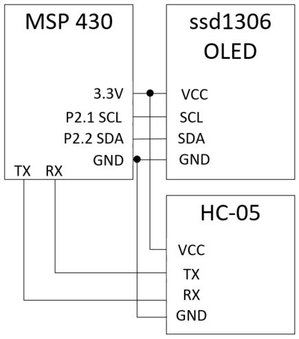
Now, let's connect the HC-05
bluetooth module back to the circuit. The purpose of this test is to
send a text message from the bluetooth terminal on your phone to the
HC-05 and display the text on the OLED module.
Make the following hardware connection.
Upload the following code to your MSP430 board
// Example 5, Phone, HC-5, and OLED display, works but only receive less than 16 characters at once from a phone. #include <Wire.h> #include "Font.h" #include <string.h> #include "images.h" #include <SoftwareSerial.h> SoftwareSerial BTserial(11,12); #define OLED_Write_Address 0x3C String readString; char* buf;
void OLED_Data(char *DATA) /* Function for sending data to OLED */ { int len = strlen(DATA); for (int g=0; g<len; g++) { for (int index=0; index<5; index++) { Wire.beginTransmission(OLED_Write_Address); /* Begin transmission to slave device */ /* Queue data to be transmitted */ Wire.write(0x40); /* For Data Transmission, C = 0 and D/C = 1 */ Wire.write(ASCII[DATA[g] - 0x20][index]); Wire.endTransmission(); /* Transmit the queued bytes and end transmission to slave device */ } } }
void OLED_Command(char DATA) /* Function for sending command to OLED */ { Wire.beginTransmission(OLED_Write_Address); /* Begin transmission to slave device */ /* Queue data to be transmitted */ Wire.write(0x00); /* For Data Transmission, C = 0 and D/C = 0 */ Wire.write(DATA); Wire.endTransmission(); /* Transmit the queued bytes and end transmission to slave device */ }
void OLED_clear() /* Function for clearing OLED */ { OLED_setXY(0x00, 0x7F,
0x00, 0x07); /* Column Start Address 0, Column End Address 127, Page
Start Address 0, Page End Address 7 */ for (int k=0; k<=1023; k++) { Wire.beginTransmission(OLED_Write_Address); /* Begin transmission to slave device */ /* Queue data to be transmitted */ Wire.write(0x40); /* For Data Transmission, C = 0 and D/C = 1 */ Wire.write(0x00); Wire.endTransmission(); /* Transmit the queued bytes and end transmission to slave device */ } }
void OLED_setXY(char
col_start, char col_end, char page_start, char page_end) /* Function
for setting cursor for writing data */ { Wire.beginTransmission(OLED_Write_Address); /* Begin transmission to slave device */ /* Queue data to be transmitted */ Wire.write(0x00); /* For Data Transmission, C = 0 and D/C = 0 */ Wire.write(0x21); /* Set Column Start and End Address */ Wire.write(col_start); /* Column Start Address col_start */ Wire.write(col_end); /* Column End Address col_end */ Wire.write(0x22); /* Set Page Start and End Address */ Wire.write(page_start); /* Page Start Address page_start */ Wire.write(page_end); /* Page End Address page_end */ Wire.endTransmission(); /* Transmit the queued bytes and end transmission to slave device */ }
void OLED_init(void) /* Function for initializing OLED */ { OLED_Command(0xAE); /* Entire Display OFF */ OLED_Command(0xD5); /* Set Display Clock Divide Ratio and Oscillator Frequency */ OLED_Command(0x80); /* Default Setting for Display Clock Divide Ratio and Oscillator Frequency that is recommended */ OLED_Command(0xA8); /* Set Multiplex Ratio */ OLED_Command(0x3F); /* 64 COM lines */ OLED_Command(0xD3); /* Set display offset */ OLED_Command(0x00); /* 0 offset */ OLED_Command(0x40); /* Set first line as the start line of the display */ OLED_Command(0x8D); /* Charge pump */ OLED_Command(0x14); /* Enable charge dump during display on */ OLED_Command(0x20); /* Set memory addressing mode */ OLED_Command(0x00); /* Horizontal addressing mode */ OLED_Command(0xA1); /* Set segment remap with column address 127 mapped to segment 0 */ OLED_Command(0xC8); /* Set com output scan direction, scan from com63 to com 0 */ OLED_Command(0xDA); /* Set com pins hardware configuration */ OLED_Command(0x12); /* Alternative com pin configuration, disable com left/right remap */ OLED_Command(0x81); /* Set contrast control */ OLED_Command(0x80); /* Set Contrast to 128 */ OLED_Command(0xD9); /* Set pre-charge period */ OLED_Command(0xF1); /* Phase 1 period of 15 DCLK, Phase 2 period of 1 DCLK */ OLED_Command(0xDB); /* Set Vcomh deselect level */ OLED_Command(0x20); /* Vcomh deselect level ~ 0.77 Vcc */ OLED_Command(0xA4); /* Entire display ON, resume to RAM content display */ OLED_Command(0xA6); /* Set Display in Normal Mode, 1 = ON, 0 = OFF */ OLED_Command(0x2E); /* Deactivate scroll */ OLED_Command(0xAF); /* Display on in normal mode */ }
void setup() { Serial.begin(9600); Wire.begin(); /* Initiate wire library and join I2C bus as a master */ OLED_init(); /* Initialize OLED */ OLED_clear(); }
void loop() { while (Serial.available()>0){ delay(10); // give a slight delay to let the serial buffer receive the full byte char c=Serial.read(); readString+=c; } if (readString.length()>0){
int str_len=readString.length()-1; // start converting the string to a
char array. Get rid of the "\0" terminator in the string.
https://www.cs.bu.edu/teaching/cpp/string/array-vs-ptr/ char char_array[str_len]; readString.toCharArray(char_array,str_len); Serial.println(char_array); // debug purpose
OLED_Data(char_array); // this code can only handle less than 16
characters once through the HC-05 readString=""; // clear the reciever to be ready for the next data } }
You may need to modify this code slightly to show the text from your phone's bluetooth module on the OLED display.
Tasks
Complete all the experiments in this tutorial. (30 points)