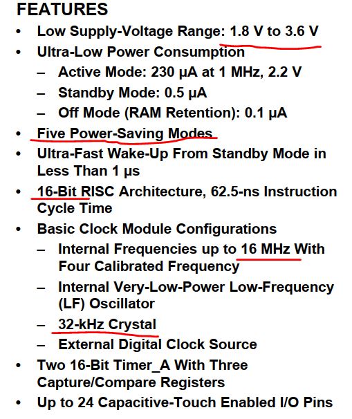
From the first paragraph in the datasheet, we can tell that this MCU is
designed for low power applications, it is a 16-bit system, it has a 32
kHz crystal clock source, and the power supply is 1.8 V - 3.6 V.
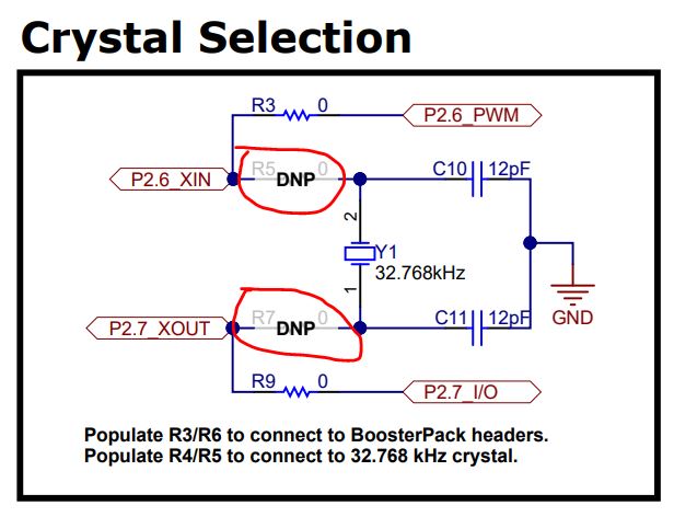
Populate R5/R7 and remove R3/R9 to enable the 32kHz low power crystal. (Refer to the schematic)
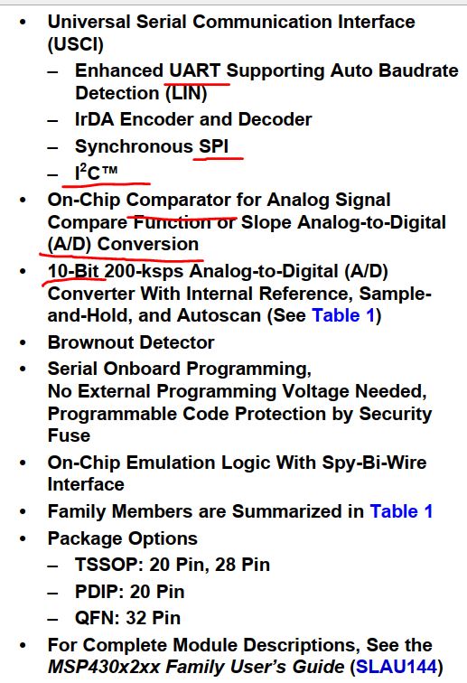
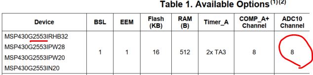
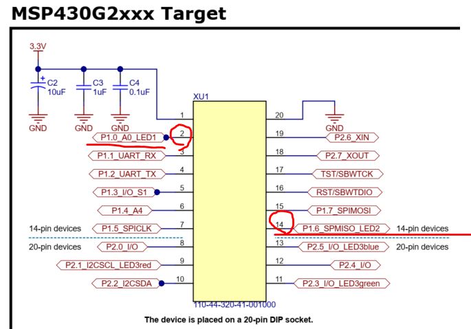
On the right-hand side, we know that this MCU has UART, SPI, I2C, and a 10-bit ADC available inside the chip.
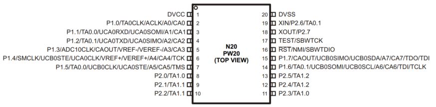
The device pinout (MSP430G2ET is the evaluation board, MSP430G2553 is the name of the MCU chip). Refer to Page 6-8 on the datasheet for the functions of the pins.
It's always important to know these critical information before you
start using the chip so you know what you will expect from this MCU.
2. Installation of the Energia IDE.
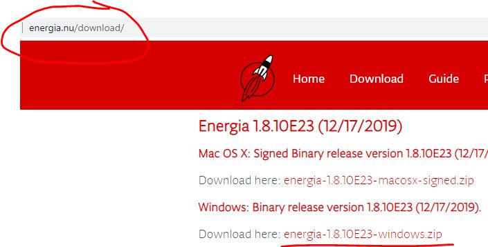
Visit Energia's website to download the newest Energia IDE.
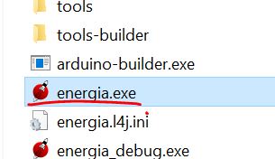
Extract the downloaded package on your C drive and double click energia.exe.
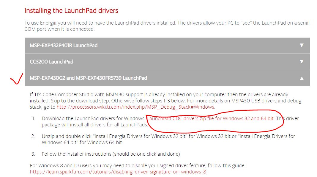
Select 'MSP-EXP430G2 and MSP-EXP430FR5739 Launch Pad'
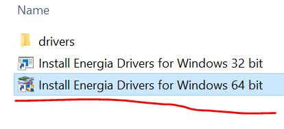
If you have a 64-bit Windows PC then do double click the following item.
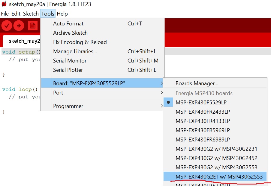
Open Energia.exe in the folder and select the correct board:
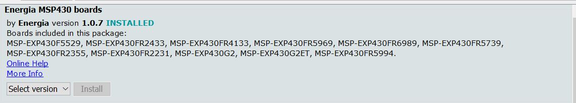
Go to Tools - Board Manager, install the newest Energia MSP430 boards. (Important)
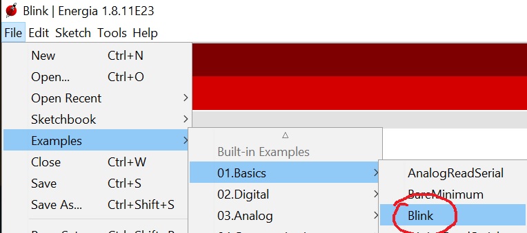
Find a blink example to test if your PC and the board communicate with each other.
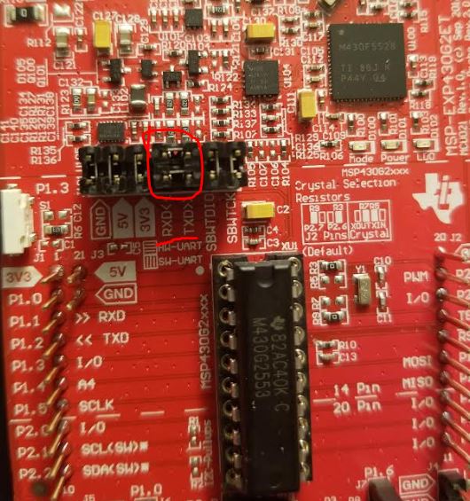
3. Serial communication
The direction of the jumpers
in the following figure doesn't affect the program to be uploaded from
the PC to the board. You can even unplug them while the code is being
uploaded to it. However, if you need to debug your code (watch the
serial data being sent back to the PC in a serial monitor), you must
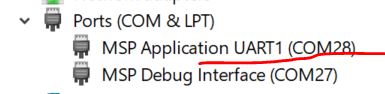
rotate the jumpers and select the UART1 COM port. The rule of thumb is just
keep the jumpers connected as what is in the following figure for
Programming and Debugging. Always use the UART1 port for any purposes.
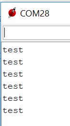
Try this simple code and open the serial monitor to verify the functionality of the board and serial communication.
Let's read some data from the ADCs and display them in the serial monitor. On the datasheet, you can see that the MCU has 8 ADC ports. The 2553 versions all have 8 ADC channels:
Can you locate the 8 ADC ports on the boad by reading Page 6 - 7 on the datasheet?
But where are P1.0 and P1.6? Ok, let's take a look at the MCU's pinout. Not too bad, only 20 pins - an entry-level MCU.
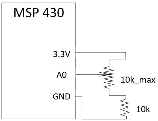
Now, let's build a voltage
divider using a potentiometer (in you box) and a 10k resistor. The
output goes to A0 of the MCU (one of the ADC inputs), let the MCU
digitize the analog voltage input at A0 and directly use the digitized
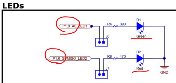
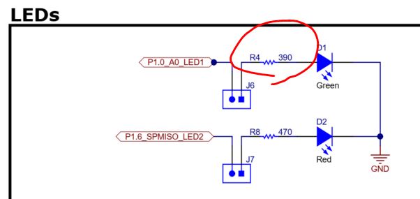
value as the time delay to blink the LED connected to Pin 14. Because the Green LED (D1) is
directly shorted to A0, when the voltage input varies, the brightness
of D1 will vary as well. Wait.... Is there a protection resistor for
the Green LED (D1)?
Yes there is! The 390 ohm
resistor is just about right. Let's code it up! It should be a pretty
simple and interesting experiment.
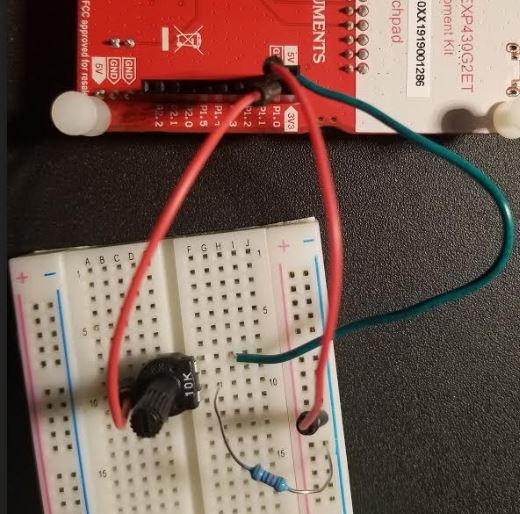
Hardware connection:
Connect from the back of the board becaue the wires available are male-to-male.
Code:
// Example 2, analog input int sensorPin = A0; // select the input pin for the potentiometer int sensorValue = 0; // variable to store the value coming from the sensor
void setup() { // declare the 14 pin as an OUTPUT: pinMode(14, OUTPUT); Serial.begin(9600); }
void loop() { // read the value from the sensor: sensorValue = analogRead(sensorPin); // turn the ledPin on digitalWrite(14, HIGH); // stop the program for <sensorValue> milliseconds: delay(sensorValue); // turn the ledPin off: digitalWrite(14, LOW); // stop the program for for <sensorValue> milliseconds: delay(sensorValue); Serial.println(sensorValue); }
Video Demonstration:
Open the serial monitor to check the maximum and the minimum possible values. Why the minimum value is higher than VDD/2?
Tasks:
Repeat all the experiments in this tutorial. (20 points)