Goals of this project: 1. Use the Arduino board to
build your prototype and use a barebone ATmega328p microncontroller for
the final product. 2. Integrate the entire
circuit onto a PCB board. 3. The DIY maze solver must
be able to complete the maze through the optimal path.
One of the simplest ways of
solving a maze with a robot is by using the Wall Follower algorithm,
also know as the left-hand rule (or right-hand rule). Forget about the
robot for a while, and suppose that you are a person inside a maze.
Finding the exit could be done just by keeping one of your hands always
touching a wall. And by “always”, we really mean always here. It
might take you a while and you might wind up taking all the wrong paths
in the maze before getting to the end but by keeping your left hand on
the wall of the maze you wind up taking every single left hand turn
(sometimes turning around completely) and, as long as you keep taking
steps forward, eventually you’ll get to the end of the maze.
2. Test
the TCRT5000 IR pair
The datasheet of IR pairs
available to you can be found here.
You must find the polarity of
the pins by reading this datasheet carefully. It won't tell you how to
make connectiosn to the pins directly but you will find answers from a
few places on your own.
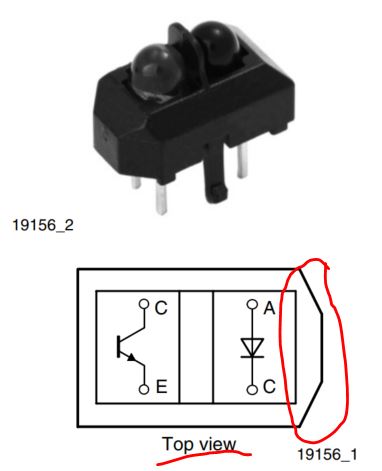
On the first page of the
datasheet, the following figures tells you the polarity and the
internal circuit of the IR pairs:
The name of the teminals are
not given but only a few letters are given. You'll learn this in any
'Microelectronics' or 'Analog Electronics' classes. C: Collector of the
BJT transistor, E: Emmitter of the BJT transistor, A: Anode of the
diode, C: Cathode of the diode. Now you have enough information to make
connections to this IR pair.
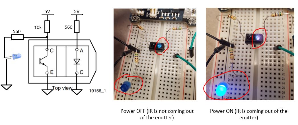
We can definitely re-use the
most part of this circuit. The resistor at the LED side is at the ~100
ohm level (I used 560 ohm in the circuit below), the purpose is just to
limit the current and protect the LED. However, on the BJT side, we
need a 10k resistor as the 'pull-up' resistor. This resistance must be
significantly higher than the ON mode of the BJT to take over all the
voltage shares in this 'Voltage Divider'.
I tested this IR pair with
the protection resistor and the pull-up resistor and it worked very
well.
First, I powered it up and
checked the IR emitter:
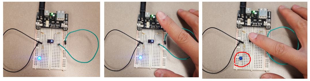
Then I use my figure to
reflect the IR from the emitter to the receiver.
The demo video can be found
below:
Task 2: Repeat the work in the demo video above, show your
result in
a VIDEO for the report.
3. Assemble and solder your
IR sensor array
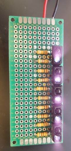
Solder the IR pairs onto a
prototype PCB board. I solded four pairs in the following figure at the
beginning and added an extra one later. I recommend at least 5 IR pairs
for this module. (I ended up with using 6 of them). My Samsung phone's camera can
visualize part of the IR spectrum so you can see the purple light in
the following figure.
To test if the receiver can
detect the reflection, I added LEDs to the circuit.
This video proves the IR
pairs are functioning.
Without an comparator, the
intensity level of the LEDs are not binary, which means depends on the
reflection intensity, the LED's brightness varies in a range. This is
pretty bad for motor control because you cannot quantify the reflection
intensity and use this intensity to control the motors' speed. We need
to add comparators to the circuit.
With comparators, the LEDs
will only have two states, ON and OFF. It is demonstrated in the
following video.
Task 3: Repeat the work in the demo video above, show your
result in
a VIDEO for the report.
4. Build the main circuit of
the car.
This car is controlled by a
CPU but not simply a DC circuit. Use the control strategy you learned
from the Elegoo Smart Car V3 to make the hardware connections. The speed of the wheels
should be controllable. Use PWM to power up the 'ENABLE' pins of the
two motor drivers on the same chip. Use L293N as the motor driver.
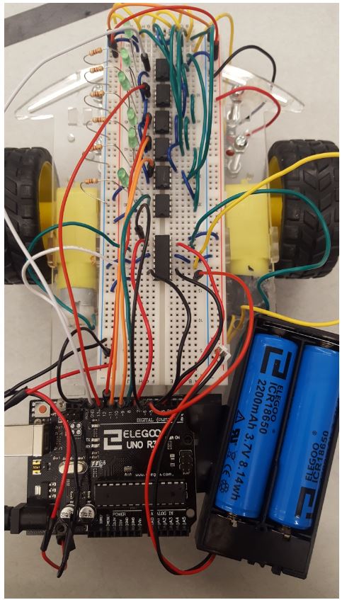
I used the batteries from the
Elegoo car kit since they are rechargable. The following figure shows
the complete circuit of the prototype. You may have noticed that I used
6 comparators which means I have 6 IR pairs at the bottom of the car.
Check out the following
videos:
Task 4: Repeat the work in the demo video above, show your
result in
a VIDEO for the report. (Use the barebone ATMega 328 chip directly on the breadboard, do not use the Arduino Uno board on the car).
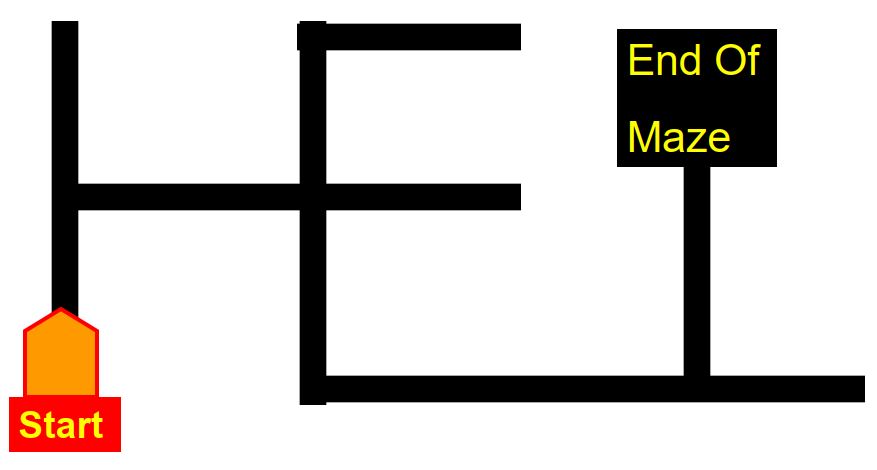
Task 5: Design the code to enable the car be able to complete the following maze.
5. Optimize the path
Task 6:
Read the following slides and optimize the path of maze for the car.
The performance of the car won' t be as good as the one sold by Pololu
but it should be able to slowly complete and optimize the path for the
maze.