In this experiment, we'll use Qt Designer to build the frame of the GUI and add functions to the frame.
1. Get started with Qt Designer.
Qt Designer is the Qt tool for designing and building graphical user interfaces (GUIs) with Qt Widgets. You can compose and customize your windows or dialogs in a what-you-see-is-what-you-get (WYSIWYG) manner, and test them using different styles and resolutions.
Widgets and forms created with Qt Designer integrate seamlessly with programmed code, using Qt's signals and slots mechanism, so that you can easily assign behavior to graphical elements. All properties set in Qt Designer can be changed dynamically within the code. Furthermore, features like widget promotion and custom plugins allow you to use your own components with Qt Designer.
Note: You have the option of using Qt Quick for user interface design rather than widgets. It is a much easier way to write many kinds of applications. It enables a completely customizable appearance, touch-reactive elements, and smooth animated transitions, backed up by the power of OpenGL graphics acceleration. If you are new to Qt Designer, you can take a look at the Getting To Know Qt Designer document. For a quick tutorial on how to use Qt Designer, refer to A Quick Start to Qt Designer.
Because there is no Qt Designer in your RPI board, so we'll use the Qt Designer in Anaconda in your Windows PC.
You will need the Qt Designer in Windows to design the GUI, then convert it to a '.py' file. Then push them to GitHub. In your RPI, clone the repository from GitHub to the RPI, run/modify/debug/test the code until it works. Finall within the Local Git Folder (with the .git folder inside), do a 'git push' operation to update the repository online. In the future, if you'd like to change the GUI appearance again in Windows, just keep the repository folder in your local drive and do a 'git pull' operation in the command line to update your local git folder.
This is a perfect example of doing 'version control' using Git. The only difference is the two branch owners are yourself.

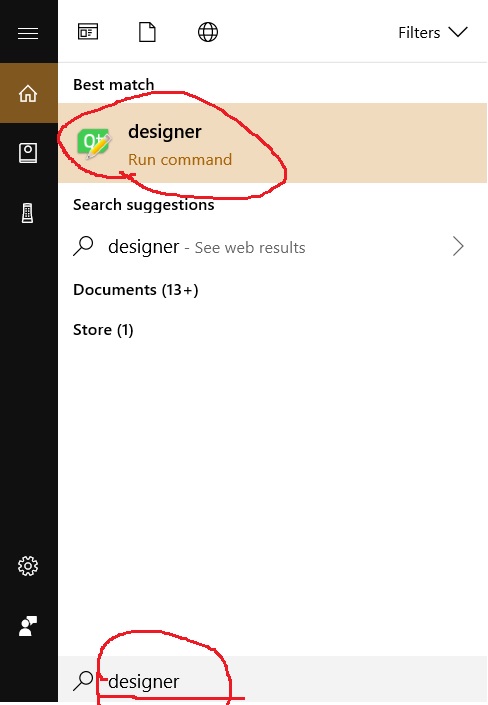
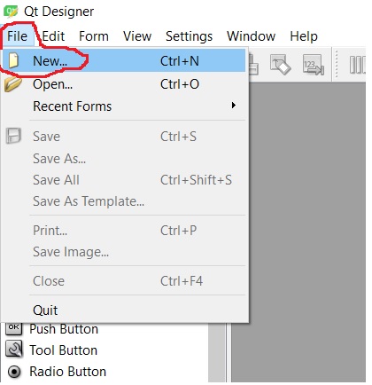
To start Qt Designer, press the Window Key on the keyboard and type 'designer':

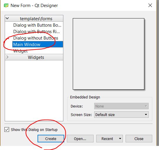
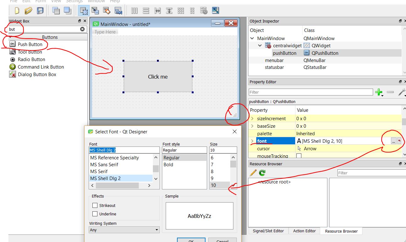
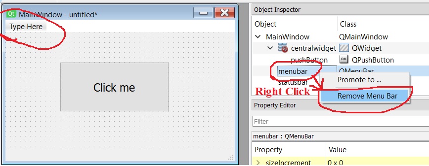
Follow all these steps to build a simple pushbutton GUI:
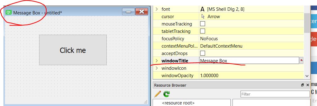
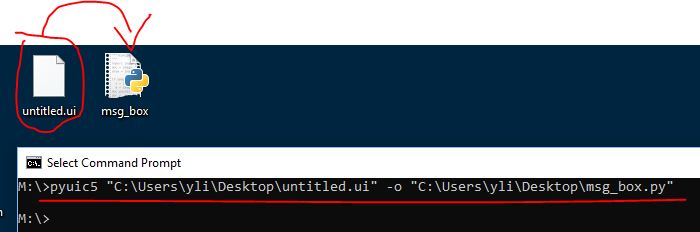
After the GUI window is done in QtDesigner, save the '.ui' file on the Desktop, in the command line, use: pyuic5 msg_box.ui -o msg_box.py to convert it into a python file.
If you use a Lab computer and don't hae the admin access. Then probably you can do this:
('yli' is my user name, you need to change it to yours)
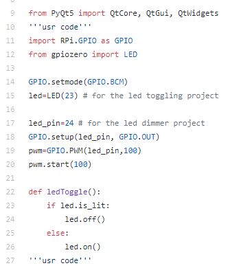
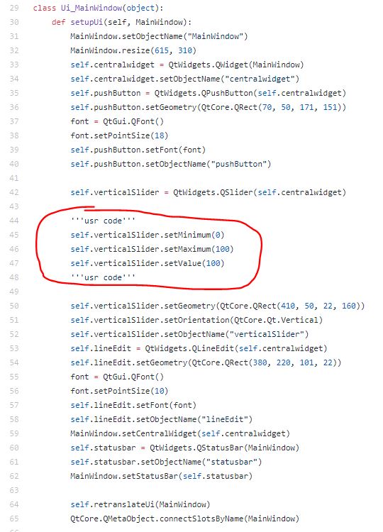
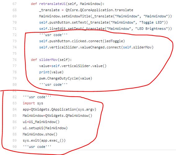
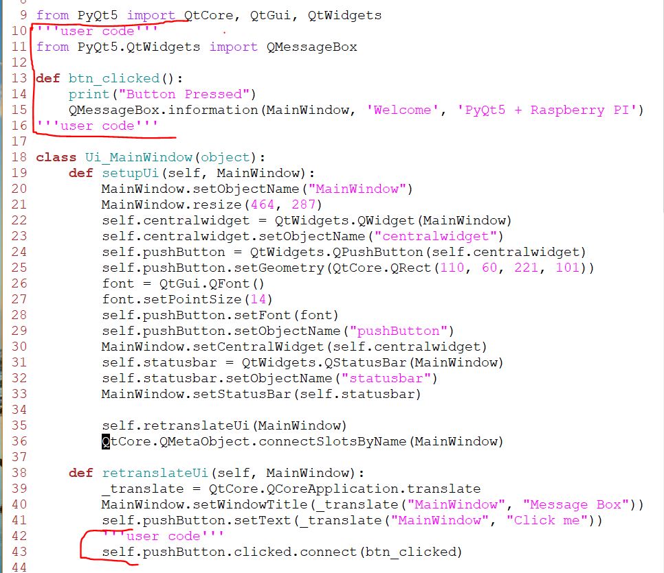
Add the the 'user code' to the '.py' file:
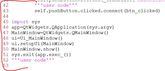
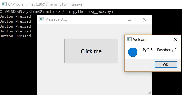
Run the code with Python you will get the following GUI pops up:
2. Use a pushbutton in the GUI to toggle the GPIO pins on the RPI board
You have used a pushbutton in the GUI in RPI to toggle a GPIO pin on the RPI board using the 'tkinter' GUI design Class. In this tutorial you learned how to design a pushbutton GUI using PyQt. Can you combine these two things you learned to make a pushbutton GUI using PyQt to toggle a GPIO on the RPI board? Use the LED to show your pushbutton on the touchpad can toggle an LED light on the circuit board. (Parts of the code in Section 3 works out for this purpose. You can use them but this section must be demonstrated separately without having any functional mudules in the code for the LED Dimmer in your code).
3. Design a Slider-Controlled LED Dimmer
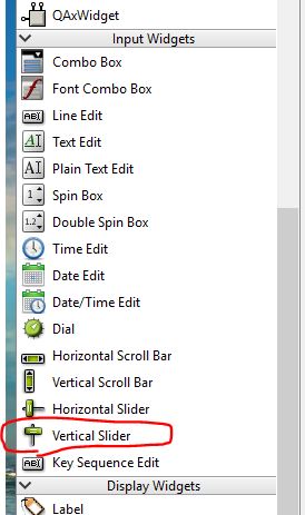
Find the Slider widget in Qt Designer:
Drag and drop the slider into the same window as your pushbutton GUI, save the '.ui' file, convert it to the '.py' file.
Push your repository to GitHub from your Windows machine.
Pull the repository to your RPI and start editing the functions for the LED Dimmer. There is something you need to know before you start coding:
What is PWM
PWM stands for Pulse Width Modulation and it is a technique used in controlling the brightness of LED, speed control of DC motor, controlling a servo motor or where you have to get analog output with digital means. The Raspberry pi GPIO pins either gives us 3.3V (when turned HIGH) or 0V (when turned LOW) and the output is a square wave signal. So if we want to dim a LED, we cannot get the voltage between 0 and 3.3V from the GPIO pin but we can change the ON and OFF time of the signal. If we will change the ON and OFF time fast enough then the brightness of the led will be changed.
Before going further, let’s discuss some terms associated with PWM.
TON (On Time): It is the time when the signal is high.
TOFF (Off Time): It is the time when the signal is low.
Period: It is the sum of on time and off time.
Duty Cycle: It is the percentage of time when the signal was high during the time of period.
So at 50% duty cycle and 1Hz frequency, the led will be high for half a second and will be low for the other half second. If we increase the frequency to 100Hz (100 times ON and OFF per second), then the led will be seen glowing at half brightness by the human eye.

Raspberry pi and PWM
The ‘RPI.GPIO’ library for Raspberry pi has function which we can use for PWM. For that, first we will need to create an object in which we will pass the parameters for the GPIO pin and the frequency that we want to use. In the below command, we created an object of name ‘pwm’ and then called the function from the library.
pwm = GPIO.PWM(21, 100)
Then we need to start the PWM. To start the PWM, we will have to give the duty cycle. In the below command, I have used the 50% duty cycle.
pwm.start(50)
If you want to change the duty cycle, then you can use the below command.
pwm.ChangeDutyCycle(80)
If you want to change the frequency, then use the below command.
pwm.ChangeFrequency(1000)
To stop the PWM, use the following command.
pwm.stop()
Now let’s move forward and change the brightness of an led.
I've done this experiment, here is the demo video: